

For HVAC systems
Soundproofing and acoustic treatment for HVAC systems
HVAC noise reaches a finished room by three separate routes: inside the duct and out of the grille, through the duct wall into the ceiling void, and through the slab from a skid mounted unit. Each route needs a different layer, and the one that gets missed is the one people complain about after handover.
- Duct lagging and enclosures
- SoundBlanket® MLV, STC 34 at 4 mm
- Low frequency and vibration
- BassBloc®, NRC 0.85 at 20 mm, 100 to 500 Hz
- Plant room lining
- Foam NRC 0.95 at 50 mm, PET felt NRC up to 0.60
- Quote
- Within 48 hours, from the equipment schedule and duct layout
Send the equipment schedule, the duct layout with sizes, the plant room location relative to occupied rooms, and how the units are mounted. We manufacture and specify materials; duct sizing, air velocity and attenuator selection are the designer's scope, and we do not carry out on site measurement, consultancy or installation ourselves.
01 / What actually goes wrong
Three paths, and a wall that stops none of them
A partition built to a good specification is bypassed by the services that pass through it. This is why HVAC noise is so often the last defect on a project: every other element was treated, and the duct and the slab were not.
-
Noise inside the duct, out of the grille
Fan noise and airflow turbulence travel along the inside of the duct and arrive in the room through the diffuser, which is an opening in the ceiling connected directly to the plant. Nothing on the room surfaces changes this. It is controlled at the fan, along the duct run, and in the box behind the grille, and the outlet itself has to be selected for the flow rate rather than lined afterwards.
-
Breakout through the duct wall
A duct running at high pressure through a ceiling void radiates along its whole length, so a corridor duct crossing over a bedroom or a cabin becomes a long thin noise source above a finished ceiling. Thermal insulation does not fix this because it has no mass. Lagging does: a resilient layer against the duct with a dense barrier wrapped over it, laps sealed.
-
The structure borne path from a skid mounted unit
An AHU, chiller, pump or rooftop unit bolted to a slab or a steel frame puts energy directly into the structure, which carries it into beams, columns and partitions and re-radiates it as a hum in rooms nowhere near the plant. It survives a heavy plant room wall, because it never used the air path. It is fixed under the unit with pads and mounts, and it is undone again by rigid pipework crossing the isolator.
02 / The build-up
Five layers, from the machine outwards
The order matters here more than on any other application. A barrier placed directly against a vibrating duct or casing is coupled to it; the resilient layer has to go in first.
-

Layer 1
The break under the unit
First, before any wrapping or lining. Pads or mounts under the AHU, chiller, pump or fan base, sized for the load at each point, with a flexible section in the pipework and the duct connection so nothing rigid crosses the isolator. Without this layer the rest of the work treats the wrong path.
Anti-vibration mounts and pads, and the sound insulation pad for under-equipment isolation. Send the unit weight and the mounting arrangement with the enquiry.
-
Layer 2
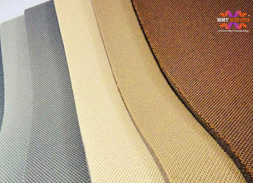
BassBloc® against the duct or the casing
The resilient, low frequency layer. On a duct it decouples the barrier above it from the duct wall and absorbs where fan and motor energy sits. Inside an AHU enclosure or a plenum box, foam does the same job for the higher frequency content. Absorption goes inside enclosures and plenum boxes, not loose in the airstream.
BassBloc® NRC 0.85 at 20 mm, 0.95 at 40 mm, to ASTM C423, effective 100 to 500 Hz, 100 kg/m³, 1800 x 900 mm rolls · Galaxy foam NRC 0.95 at 50 mm · Pyramid foam NRC 0.90 at 50 mm
-
Layer 3
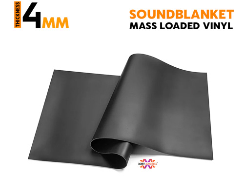
SoundBlanket® as the outer barrier
The mass layer, wrapped over the resilient layer on a duct, fixed in the plant room partition, and built into the AHU enclosure panel. It works by mass, so laps are overlapped and sealed and every penetration is closed. A wrap left open at a seam or stopped short at a hanger leaks along that line.
STC 30 at 2.5 mm, STC 34 at 4 mm, to ASTM E90. 2100 kg/m³. Class A surface burning to ASTM E84. Custom 1 to 10 mm. Sheets 8 x 4, 16 x 4 and 32 x 4 ft. Dispatch 2 to 5 days in India, 7 to 10 for export.
-
Layer 4
The room side lining
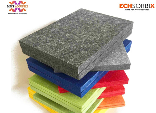
A plant room is small, hard and full of machines, so it raises its own level and pushes more energy at every wall, door and penetration. Lining the walls and soffit reduces that build-up and makes the room workable for the people who have to maintain it. PET felt survives a service environment better than an exposed soft absorber.
PET felt panels NRC 0.30 at 9 mm, 0.40 at 12, 0.50 at 18, 0.60 at 24 mm, and 0.90 over 20 mm BassBloc®. 1200 to 3600 GSM, 1220 x 2440 mm, 40+ colours, 3 to 7 day lead time. Metal ceiling tiles, up to NRC 1.0 with fleece backing, where the face must be washable.
-
Layer 5
Penetrations, and the plant room door
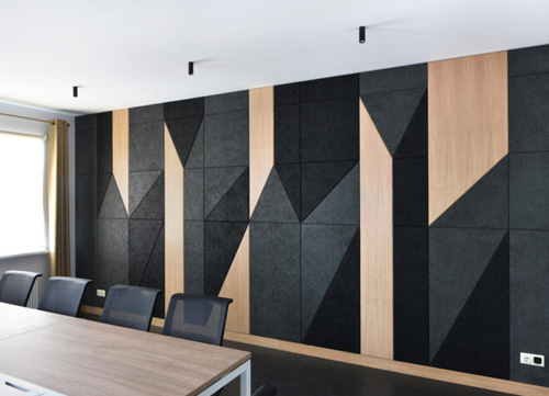
Every duct, pipe, drain and cable tray that crosses the isolating line is a hole in it, and so is the plant room door. This is the cheapest layer on the job and the one most often left out, which is why a heavy plant room wall so often performs like a light one.
EPDM perimeter seal, 6 x 6 mm D-type · Silicone bottom seal, 920 x 15 mm · Perimeter, bottom and drop-down seals, 18 ft per roll · Soundproof curtain, STC 30, over an opening that has to stay usable
Layer order by element
| Element | From the source outwards | What it is for |
|---|---|---|
| Duct over an occupied room | BassBloc® 20 mm wrapped against the duct, SoundBlanket® 4 mm over it, laps sealed | Breakout through the duct wall |
| AHU enclosure panel | Frame, SoundBlanket® 4 mm, then foam 50 mm on the inner face | Mass to block, lining so the enclosure does not amplify |
| Plant room wall to an occupied space | SoundBlanket® 4 mm in the partition, BassBloc® 20 mm in the cavity, PET felt on the plant room face | Airborne transfer to the room next door |
| Unit base, skid or rooftop frame | Pads or anti-vibration mounts, flexible pipe and duct connections | The structure borne path |
| Riser and shaft wall | SoundBlanket® on the shaft face, PET panels where the shaft is accessible | Vertical flanking between floors |
| Ceiling void above a finished room | SoundBlanket® carried over the partition line, felt tiles or baffles on the visible face | Closes the path over the top of the wall |
| Plant room door and penetrations | Solid leaf, perimeter and bottom seals, every service entry sealed back to the wall | The weakest opening sets the result |
Duct sizing, air velocity, attenuator selection and the room noise target are the mechanical designer's and the acoustic consultant's scope. We supply and specify the lagging, lining, barrier, sealing and isolation materials. More on structure borne noise in machine rooms.
03 / Zone by zone
From the unit to the grille, in the order the sound travels
-
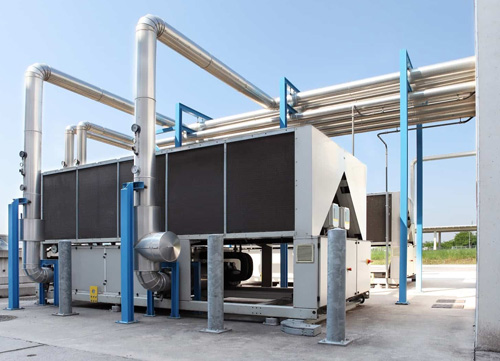
The air handling unit
The source for both of the airborne paths. The fan pushes noise into the duct and radiates through the casing into the plant room, and the unit vibrates into whatever it stands on. Line the enclosure so it does not amplify, add mass on the panel, and isolate the base before anything else.
- Galaxy foam 50 mm, NRC 0.95, lining the enclosure interior
- SoundBlanket® 4 mm, STC 34, in the enclosure panel
- BassBloc® 20 mm where the low frequency content dominates
- Insulation pads and anti-vibration mounts under the base
-
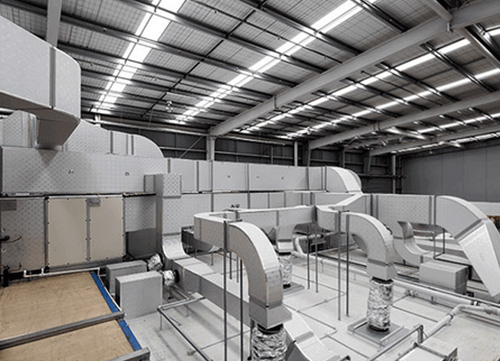
The plant room
A small hard room containing everything that runs continuously. It has to be lined so the room stops raising its own level, and sealed so the level it holds does not arrive next door. The door and the service penetrations are almost always the weakest parts of it.
- PET felt panels, NRC up to 0.60, on walls and soffit
- SoundBlanket® 4 mm in the partition to occupied areas
- Perimeter and bottom door seals, silicone and EPDM
- Metal ceiling tiles, up to NRC 1.0 with fleece backing, where the face must be washable
-
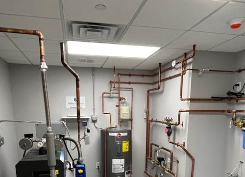
The wall between the mechanical room and the occupied space
This is a partition problem with services running through it. Build the mass into the wall, fill the cavity, carry the barrier up to the deck so nothing passes over the ceiling line, and seal every duct and tray crossing. A single unsealed cable entry can set the limit for the whole wall.
- SoundBlanket® 4 mm, STC 34, in the partition and above the ceiling line
- BassBloc® 20 mm, NRC 0.85, in the cavity
- Why insulation alone is not a barrier
- Building a wall for a high STC target
-
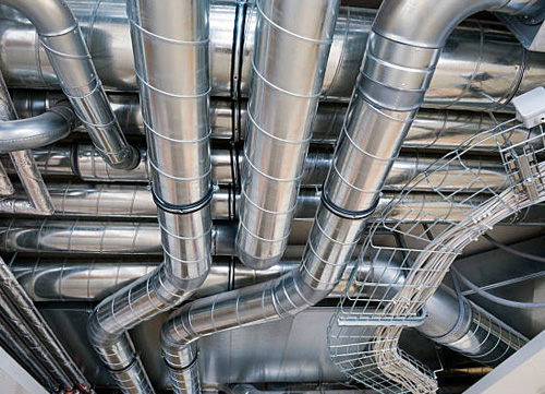
Ducts, risers and shafts
Lagging is worth doing where the duct passes over or beside a quiet room and nowhere else, so the material goes on the runs that matter rather than the whole system. Risers do the same thing vertically: a shaft connects every floor it passes, so the shaft wall and the openings into it need the same attention as a partition.
- BassBloc® 20 mm wrapped against the duct as the resilient layer
- SoundBlanket® 4 mm as the outer barrier, laps sealed
- Custom MLV thicknesses, 1 to 10 mm, for tight void depths
- SR adhesive, 20 ml per sq ft, for bonded build-ups
-

The ceiling void, the plenum box and the grille
The last few metres, and the part the occupant actually hears. Noise arrives either out of the diffuser or through the ceiling from the void above it, and the void is also the route by which sound flanks over a partition from the next room. Line the plenum box behind the outlet, treat the void, and keep the visible ceiling absorbent enough that what does arrive is not amplified by a hard room.
- Foam lining, NRC 0.95 at 50 mm, inside the plenum box behind the grille
- Felt ceiling tiles, NRC 0.30 to 0.60, 600 x 600 and 1200 x 600 mm
- Felt baffles and clouds where services stay exposed
- Fibreglass ceiling tiles, 100 kg/m³, 15 and 20 mm, Class A to EN 13501-1
-
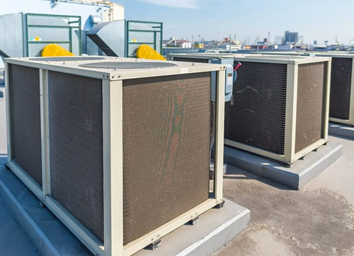
Rooftop and skid mounted units
A unit on a roof slab or a steel frame is the clearest case of the structure borne path: the airborne noise goes outside where few people are, and the vibration goes down through the structure into the top floor. The work is at the base and at the connections, not on the walls of the room below.
- Anti-vibration mounts and pads under the skid or frame
- Sound insulation pads under smaller equipment
- SoundBlanket® on the enclosure or screen where a boundary is close
- Acoustic screens where a full enclosure would block service access
04 / What we see go wrong
Six failures that show up only after handover
-
The room is treated, the duct is not
Panels go on the walls of the complaining room while the noise keeps arriving out of the diffuser and through the ceiling. The path was never across the room.
-
Thermal insulation used as lagging
A light insulation wrap has almost no mass, so breakout through the duct wall is barely changed. Lagging needs a resilient layer plus a dense barrier over it.
-
Barrier wrapped straight onto the duct
With no resilient layer underneath, the barrier is coupled to the duct wall and moves with it. The order of the two layers is not optional.
-
Mounts fitted, then bridged by rigid pipework
A bolted pipe, a conduit or a grouted frame across the isolator reinstates the structure borne path, and the hum reappears in rooms far from the plant.
-
The plant room door and penetrations left open
A heavy plant room wall with an unsealed door, duct crossing or cable tray performs like a light one. Sealing is the cheapest part of the whole job.
-
Acoustics added after the ceiling closes
Lagging a duct and isolating a unit are void and plant room operations. Doing the same work through a finished ceiling, in an occupied building, costs several times more.
05 / Specifications
Tested performance, with the standard it was measured to
| Product | Tested performance | Test standard |
|---|---|---|
| SoundBlanket mass loaded vinyl | STC 30 at 2.5 mm, STC 34 at 4 mm; 2100 kg/m³ | ASTM E90 |
| Echsorbix PET felt panels | NRC 0.30 at 9 mm, 0.40 at 12 mm, 0.50 at 18 mm, 0.60 at 24 mm | ASTM C423 / EN ISO 354 |
| BassBloc low-frequency absorber | NRC 0.85 at 20 mm, 0.95 at 40 mm; 100 kg/m³ | ASTM C423 |
| MMT Acoustix acoustic foam | NRC 0.90 at 50 mm (Pyramid); 0.95 at 50 mm (Galaxy) | ASTM C423 |
Test reports are issued with project supply. NRC and STC are the figures we publish and stand behind. Room noise levels, duct attenuation calculations and insertion loss for a finished installation are the scope of an acoustic consultant and the mechanical designer, not figures we publish. The full set of reports is listed on the certifications page.
06 / How we can help
What we do, and what we do not
-
We do
- Manufacture the lagging, lining, barrier, sealing and isolation materials at the Palwal plant, Haryana
- Turn an equipment schedule, a duct layout and a plant room section into a specified build-up and a priced BOQ, usually within 48 hours
- Supply test reports, technical data sheets and specification text for tender documents
- Cut and make up panels, liners and enclosure faces to size, including repeat OEM supply for AHU builders
-
We do not
- Size ducts, select attenuators or calculate room noise levels
- Carry out on site measurement, noise surveys or acoustic consultancy
- Install or supervise execution. We manufacture and supply the system
-
We refer
We work with associated acoustic consultants and installers across India. Where a project needs a duct noise calculation, a room noise target verified by measurement, or execution on site, ask us when you send the drawings and we will put you in touch.