
Test and measurement
Anechoic Chambers: Materials, Design, and Purpose Explained
How a room is engineered to remove every reflection and almost every trace of outside noise, and what that costs in structure, depth and services.
A speaker manufacturer once sent us frequency response curves taken in a meeting room they had lined with foam. The curves looked plausible until you put three of them side by side. The same driver, measured on three different days, showed a 4 dB spread between 200 Hz and 500 Hz. Nothing was wrong with the driver. The room was answering back, and the answer changed with the furniture, the door position and the time of day.
That is the problem an anechoic chamber exists to remove. It is not a quiet room with better foam. It is a measurement instrument, and like any instrument it is specified by the error it is allowed to introduce. Everything else, the wedge depth, the wall mass, the floating slab, the ventilation, follows from that one requirement.
Why the room has to be built twice, not once
Two completely separate acoustic jobs are happening in an anechoic chamber and people routinely collapse them into one. The first is absorption: the inner surfaces must not reflect the sound the device under test radiates. The second is isolation: outside noise must not reach the microphone. Absorptive material does almost nothing for the second job, and isolating mass does nothing at all for the first.
So the chamber is effectively two structures. The outer shell is a heavy, multi-layered assembly targeting STC 60+, usually concrete or a double-wall construction, with SoundBlanket MLV laid inside the wall and ceiling build-ups to add limp mass without adding depth. Inside that shell sits the absorptive lining, which carries no isolation duty at all. Clients often want to spend on the lining and save on the shell, which is the wrong way round.
A useful test of whether a specification has been thought through: ask what the background noise target is. If the answer is a Noise Criterion of 15 or lower, the shell has been taken seriously. If nobody has set a number, the chamber has been designed as decoration.
How much absorption does a free field actually demand?
A free field condition means a sound wave leaves the source and never comes back. In practice that means the boundary has to absorb essentially all of the energy that hits it, which is why chamber linings are specified at NRC 1.0 rather than the 0.85 or 0.90 that would be excellent anywhere else in a building.
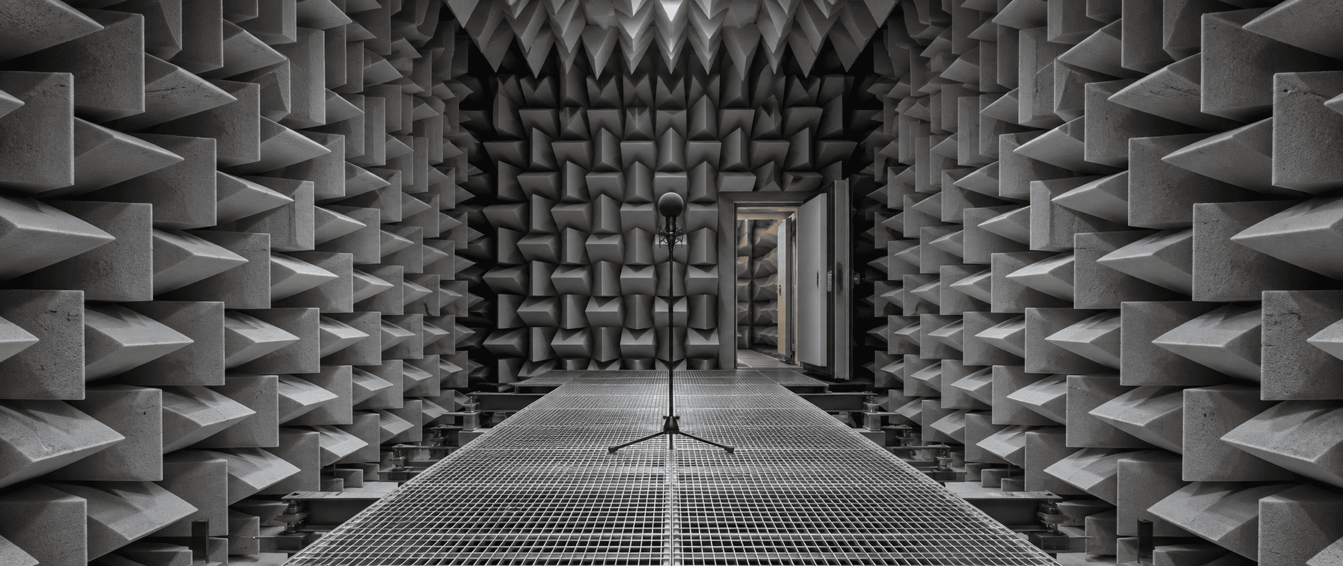
That figure is not achieved by a flat panel. It is achieved by geometry. The lining is built from high-density open-cell polyurethane foam cut into pyramid or wedge profiles, typically 12 to 36 inches deep depending on the frequency range the chamber has to cover. The taper presents a gradual change in acoustic impedance rather than an abrupt one, so the wave is drawn into the material instead of bouncing off its face, and the depth sets how low in frequency that behaviour still holds. A chamber for speech and mid-band product testing can live at the shallow end of that range. One for low-frequency automotive work cannot, which is why larger chambers support testing at lower frequencies: the wedges get longer and the clear working volume has to survive them.
Our acoustic foam wedge programme is cut to the depth a given test standard requires rather than to a catalogue size, because the cut-off frequency of the room is decided here and nowhere else.
Where does the low frequency energy end up?
Long wavelengths are the part everyone underestimates. A 60 Hz wave is roughly 5.7 metres long, and no practical wedge is a quarter of that. Structural corners are where that energy collects, so corner treatment is a separate specification, not a continuation of the wall lining.
BassBloc, at NRC 0.85, in 20 mm and 40 mm, is installed at the structural corners behind the wedge field to take out the low-end hum the wedges alone leave in the room. In a semi-anechoic build, where the floor is deliberately reflective, it matters more still: you have removed one of the six absorbing surfaces.
Why the floor is the hardest surface to solve
Every other surface can simply be covered. The floor has to be walked on, and in automotive work a vehicle or an engine rig has to stand on it. The standard answer is an elevated floor of steel grating or mesh over an absorptive pit, with the wedge field continuing below the walking plane. Acoustically the floor disappears. Practically, you still have a working surface.
Underneath all of it, the chamber is decoupled from the building. Floating foundations stop footfall, lift machinery, road traffic and plant vibration arriving through the structure, the one path no amount of absorption will touch. This is vibration isolation in the literal sense: the chamber sits on resilient supports and shares no rigid connection with the slab around it. Skip it and the room will meet its reverberation target and still fail its background noise target.
Can the chamber stay silent with the services running?
An empty chamber is easy. A chamber with light, air and a door is not.
- Ventilation: air has to move slowly through oversized, lined attenuators, because the NC 15 target is usually broken by air turbulence rather than by the plant itself.
- Lighting: fittings must be silent and vibration-free, with no transformer hum and no fan-cooled drivers inside the chamber volume.
- Doors: heavy gasketed acoustic doors rated STC 60+ to match the shell, because a door is a hole in the wall until it is sealed properly.
- Seals: compression sealing on every leaf and frame, using EPDM perimeter seals and drop sweeps so that the closed door performs anything like its rating.
This is where most chambers lose their last few decibels, and it is almost always a services problem rather than a materials one.
What an automotive R&D chamber in Pune needed
A Pune automotive group asked for a chamber to test engine components and cabin noise without reflections corrupting the data. The requirement was blunt: they needed to trust a measurement to a fraction of a decibel, repeatedly.
-
Shell and isolation
Walls built up with SoundBlanket MLV at 4 mm, STC 34, inside the assembly to add mass to the isolating construction before any absorptive work began.
-
Wall and ceiling lining
Foam wedges at NRC 1.0 across walls and ceiling, with deep wedge panels on the ceiling to cover the full frequency range rather than just the mid-band.
-
Floor
A floating mesh floor over a foam pit, so the working surface stayed usable while the boundary stayed acoustically transparent.
-
Verification
The finished room measured an RT60 below 0.1 seconds across the frequency range, which was the point at which component and cabin measurements became repeatable.
The same principles turn up in speaker, microphone and headphone development, in aerospace component testing, in radar and sonar signature work, and in psychoacoustic research on hearing thresholds. The application changes. The physics does not.
What to settle before anyone quotes you a wedge price
Start with three numbers, in this order. First, the lowest frequency you need valid data at, because that sets wedge depth and therefore the internal volume you lose. Second, the background noise target, because NC 15 decides the shell, the floating slab and the ventilation strategy, and none of those can be retrofitted. Third, the clear working dimensions you need with the wedges installed, measured tip to tip, not wall to wall.
Then decide between full anechoic and semi-anechoic. A semi-anechoic chamber with a hard reflective floor is the right answer for a great deal of automotive and appliance work and costs considerably less to build. Send us the test standard you are working to and the site constraints, and we will work the wedge depth, isolation build-up and corner treatment back from it.
Products used in this article
Specifications and technical data on each product page. Smaller quantities ship from our online store.
- Acoustic Foam Wedges and Bass Traps NRC 0.90, wedge profiles cut to depth
- SoundBlanket Mass Loaded Vinyl STC 30 at 2.5 mm, STC 34 at 4 mm, 2100 kg/m3
- BassBloc Sound Absorber NRC 0.85 to ASTM C423, 20 mm and 40 mm
- EPDM Perimeter Seals and Door Sweeps Self-adhesive, closes the door gap
- Vibration Isolation and Spring Mounts Floating slabs and decoupled chamber structures
Visit Online Store opens mmtacoustixonline.com in a new tab. For project quantities, BOQ support or export orders, use the quote form.